Mechanized Loop Test
One interesting thing about shared distribution subloops is that we are able
to get information about them through Qwest's Mechanized Loop Test (MLT)
system. This page describes the MLT system. We note the following section of
the FCC rules:
47 CFR section 51.319(h)(7)(i) Incumbent LECs must provide, on a
nondiscriminatory basis, physical loop test access points to requesting
carriers at the splitter, through a cross-connection to the competitor's
collocation space, or through a standardized interface, such as an intermediate
distribution frame or a test access server, for the purposes of loop testing,
maintenance, and repair activities.
The MLT system permits us to obtain a real-time actual measurement for one
of our subloops without having to go to the line to do the measurements. With
MLT, we open a web browser to visit a Qwest server. We specify the telephone
number to be tested. The MLT system breaks the connection between the loop and
the central office line card (in our case it is a loop carrier box line card).
It tests "outwards," measuring resistance, capacitance, impedence and
voltage on the loop in the direction of the end user. It also tests
"inwards," checking for presence of dial tone at the loop terminals
of the line card and the ability to "break" dial tone. When the test
is finished the loop is reconnected to the line card. This is all done in an
automated way and does not require any manual steps by Qwest personnel.
Interestingly, Qwest says it does not do automated proactive MLT testing for
"pair gain" lines.
To use the MLT system it is first necessary to gain access to the
Customer Electronic Maintenance and Repair (CEMR) system. This
requires being an interconnected carrier with Qwest, and requires getting a
Qwest cryptographic certificate if you don't already have one, and requires
getting the certificate linked to the CEMR system.
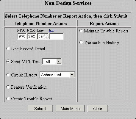
To use MLT, first log into CEMR and select "Non-Design Services,"
as shown below. Fill in a telephone number (one of your shared lines), select
"Send MLT Test Full", and click "Submit".
After a while (3 to 10 minutes), if all goes well, a report will appear.

 |
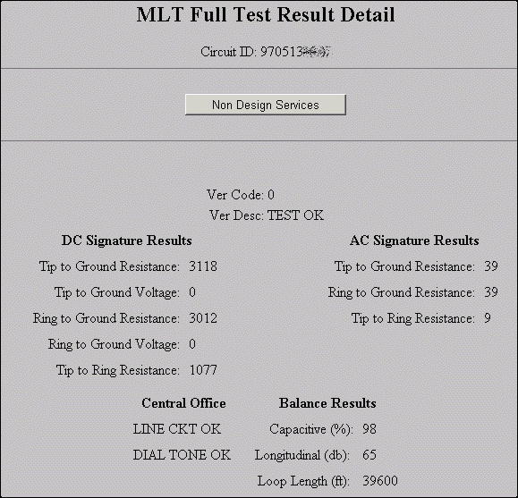
A typical test report is at the lower left. Here is a
discussion of the fields in the report.
Ver Code. This is a one- or two-character alphanumeric code which
indicates the test results.
Ver Desc. This is a text description of the test results, and it
corresponds to the "Ver Code." The usual description is "test
OK" but if there is something wrong with the line there will be some other
description.The DC resistance-to-ground measurements, which are in kilohms,
reveal leakage if any. The values in this report, in excess of 3 megohms, are
typical good values. Our loops are all in the range of 2.2 meg to 3.5 meg for
tip-to-ground and ring-to-ground.
We have never seen a value higher than 3.5 meg and many readings that we
have seen are exactly 3.5 meg. This suggests to us that the MLT ohmmeter tops
out at 3.5 megohms. Qwest has confirmed that MLT never reports a figure higher
than 3.5M.
Voltage-to-ground values should be zero and in this case they are. All of
our loops test "zero" for tip-to-ground and ring-to-ground. Nonzero
values suggest a cross to another line.
DC tip-to-ring resistance, for a line that is on-hook, should be quite high. In
this case the value is over 1 megohm which is fine. This ohmmeter also seems to
top out at 3.5 megohms. Our loops all measure between 1.1 meg and 3.5 meg.
The AC signature results are inadequately documented by Qwest. We speculated
that they represent impedence (rather than resistance) at some frequency. Qwest
has confirmed that it is an impedence measurement, and has explained that it is
measured at 24 Hz. We suspected the units are kilohms, and Qwest confirms this.
The tip-to-ground and ring-to-ground numbers for our loops are all in the range
of 32 to 40. The tip-to-ring numbers for our loops are all in the range of 7 to
18. One source suggests to us that MLT considers T-R impedence of between 1 and
20 to be okay, and that a REN of 1 or higher yields a T-R figure of 20 or
lower.Capacitive balance compares the capacitance-to-ground for the tip and
ring wires and provides a percentage of the smaller to the larger. All of our
loops are in the range of 98 to 99. Qwest says that the pass/fail criterion is
95%.
Longitudinal balance is expressed in decibels. Every MLT test we have ever
performed that gave a longitudinal balance figure has always said exactly 65
decibels. We suspect the number is a place-holder and doesn't mean anything.
Qwest says this is noise-to-ground minus the noise metallic, and that a larger
value means less perceived noise. Qwest says the criterion is 50 dB.
The "central office" results in this report are "line ckt
OK" and "Dial tone OK." These are inadequately documented by
Qwest. We suspect that "dial tone OK" means that the MLT system heard
a dial tone coming from the line card and was able to break the dial tone.
"Line ckt OK" clearly is an abbreviation for "line circuit
OK" but we don't know what Qwest means by this in technical terms.We
choose to perform an MLT full test when each shared distribution subloop is put
into service, yielding baseline values which can be compared with readings at
later times.
|
Understanding the "loop length" measurements. The loop
length in the MLT reports is said to be in feet. We have done measurements and
have determined that the longest copper loop for any home in our neighborhood,
from the loop carrier box to the end user, is at most only about 14,000 feet.
Yet the MLT results we have received give no loop shorter than about 39,700
feet and gives some measurements as long as about 49,000 feet. So every loop we
have tested gives an MLT loop length figure that is tens of thousands of feet
longer than the true loop length.
One source of this unexpectedly large MLT-measured loop length may be the
distance from the loop carrier box to the Dillon central office. Qwest has not
adequately documented this aspect of the MLT test reports, but we gather from
other sources that the MLT system may do its job by making a connection at the
loop carrier box between (a) the copper loop going to the end user and (b) a
copper loop going to the Dillon central office where the MLT measuring
equipment (voltmeter, ohmmeter, impedence meter and capacitance meter). In our
case the loop carrier box is some 17,000 feet from the central office. Stated
differently, we gather that the MLT system may do its tests by adding 17,000
feet of copper to the copper loops which connect each end user to the loop
carrier box.
But this still leaves the MLT-measured loop lengths at odds from the actual
lengths. For example the loop tested above has an actual length, from end user
to loop carrier box, of about 8,000 feet. Adding 17,000 feet of copper from the
loop carrier box to the central office would yield a total of about 25,000
feet. Yet the MLT report says the loop is 39,600 feet long. That would leave
about 15,000 feet of extra loop length; the MLT figure is some 50% larger than
the actual figure.
Qwest says this:
MLT calculates loop length from the AC capacitance measurements.
Loop Length is only returned with a Test OK or an Open Out condition. Because
MLT is calculating distance based on test measurements, circuits on Pair Gain
must be interpreted differently [than loop length measurements for all-copper
circuits]. Depending on how the MLT equipment is configured for a particular
Remote Terminal (RT), an MLT test on a Pair Gain circuit may return: 1. The
length from the RT (this is pretty rare); 2. The length from the Central
Office; 3. A length that has no correlation to actual loop length. All loops
tested from a single RT will generally have the same type of measurement
returned and will be "off" by a similar amount.
We have made baseline MLT measurements and have kept records of the
MLT-measured loop lengths. We figure that even if the MLT figures are off by
50% from the actual values, we will still be able to use the MLT-measured
values to get some rough indication of the location of the trouble.
We did some experiments, intentionally breaking a few of the POTS lines at
our splitter for a brief interval, and running the MLT test while the line was
broken, to see what MLT-measured lengths we get. We found that a complete open
at the splitter will yield MLT-measured loop lengths in the range of 36,100 to
37,000 feet. This is notably smaller than the number of feet reported by MLT
for known good loops, in the range of 39,700 to 49,000 feet. We figure this may
help us to remotely diagnose the cause of a POTS outage due, say, to a break at
our splitter.
Understanding some of the MLT error messages. For two of our
circuits, the MLT results were "34 Possible invalid access." This
meant the MLT system was not getting a proper metallic connection to the loops.
We complained and Qwest fixed it.
For three of our loops, the MLT results are "55 Pair gain channel
failure." According to Qwest, this means either an actual trouble on the
line or a failure in the MLT system. We have complained about this but it has
not yet been fixed.

